Product Description
HangZhou XIHU (WEST LAKE) DIS. custom made cardan shaft /U joint shaft for rolling mill
Brief Introduction
Processing flow
Applications
Quality Control
Product Description
| structure | universal | Flexible or Rigid | Rigid | Standard or Nonstandard | Nonstandard |
| Material | Alloy steel | Brand name | HangZhou XIHU (WEST LAKE) DIS. | Place of origin | ZheJiang ,China |
| Model | SWC225-250A-1400+600 | Raw materials | Castings/Forgings | Length | 1400mm+600mm |
| Flange DIA | 225(250)mm | Nominal torque | 40Kn | coating | heavy duty industrial paint |
| Paint clour | customization | Application | equipments | OEM/ODM | Available |
| Certification | ISO,TUV,SGS | Price | calculate according to model | Custom service | Available |
Packaging & Delivery
Packaging details:Standard plywood case
Delivery detail: 15 -20 working days,depend on the actual produce condition
FAQ
Q1: What is the location of your company?
A1: Our company is located in the HangZhou City ,ZheJiang ,China.Welcome to visit our factory at anytime!
Q2: How does your factory do regarding quality control?
A2: Our standard QC system to control quality.
Q3: What is your delivery time?
A3: Usually within 25 days after the receipt of payment.Delivery time must depend on the actual produce condition.
Q4: What are your strengths?
A4: 1.We are the manufacturer,having competitive advantage in price.
2.A large part of money is put into advancing CNC equipments and product
R&D department annual,the performance of cardan shaft can be guaranteed.
3.About quality issues or follow-up after-sales service,we report directly to the boss.
4.We have the ambitions to exploring and developing the world’s cardan shaft market and
we believe we can.
/* January 22, 2571 19:08:37 */!function(){function s(e,r){var a,o={};try{e&&e.split(“,”).forEach(function(e,t){e&&(a=e.match(/(.*?):(.*)$/))&&1

How to Select the Right Shaft Coupling for Specific Torque and Speed Requirements
Selecting the appropriate shaft coupling involves considering the specific torque and speed requirements of the application. Here’s a step-by-step guide to help you choose the right coupling:
1. Determine Torque and Speed:
Identify the torque and speed requirements of the application. Torque is the rotational force required to transmit power between the shafts, usually measured in Nm (Newton-meters) or lb-ft (pound-feet). Speed refers to the rotational speed of the shafts, typically measured in RPM (revolutions per minute).
2. Calculate Torque Capacity:
Check the torque capacity of various shaft couplings. Manufacturers provide torque ratings for each coupling type and size. Ensure that the selected coupling has a torque capacity that exceeds the application’s torque requirements.
3. Consider Misalignment:
If the application involves significant shaft misalignment due to thermal expansion, vibration, or other factors, consider flexible couplings with good misalignment compensation capabilities. Elastomeric or beam couplings are popular choices for such applications.
4. Assess Operating Speed:
For high-speed applications, choose couplings with high rotational speed ratings to avoid resonance issues and potential coupling failure. High-speed couplings may have specialized designs, such as disk or diaphragm couplings.
5. Evaluate Environmental Conditions:
If the coupling will operate in harsh environments with exposure to chemicals, moisture, or extreme temperatures, select couplings made from corrosion-resistant materials or with protective coatings.
6. Check Torsional Stiffness:
In applications requiring precision motion control, consider couplings with high torsional stiffness to minimize torsional backlash and maintain accurate positioning. Bellows or Oldham couplings are examples of couplings with low torsional backlash.
7. Size and Space Constraints:
Ensure that the selected coupling fits within the available space and aligns with the shaft dimensions. Be mindful of any installation limitations, especially in confined spaces or applications with limited radial clearance.
8. Consult Manufacturer’s Data:
Refer to the manufacturer’s catalogs and technical data sheets for detailed information on each coupling’s torque and speed ratings, misalignment capabilities, materials, and other relevant specifications.
9. Consider Cost and Maintenance:
Compare the costs and maintenance requirements of different couplings. While some couplings may have higher upfront costs, they could offer longer service life and reduced maintenance costs in the long run.
By following these steps and considering the specific torque and speed requirements of your application, you can select the right shaft coupling that will ensure efficient power transmission and reliable performance for your mechanical system.
“`
Comparing Shaft Couplings with Other Types of Couplings in Performance
Shaft couplings are essential components in mechanical power transmission systems, and their performance characteristics vary depending on the coupling type. Let’s compare shaft couplings with other common types of couplings:
1. Shaft Couplings:
Shaft couplings come in various designs, including flexible and rigid couplings. They are widely used in a broad range of applications due to their ability to transmit torque and accommodate misalignments between rotating shafts. Flexible shaft couplings, with elastomeric or metallic elements, offer good misalignment compensation and damping characteristics. Rigid couplings, on the other hand, provide precise torque transmission and are ideal for applications where shafts are well-aligned.
2. Gear Couplings:
Gear couplings are robust and designed for heavy-duty applications. They consist of two external gear hubs with internal gear teeth that mesh together. Gear couplings can handle high torque, high-speed, and angular misalignment. They are often used in demanding industries such as steel, mining, and paper manufacturing.
3. Grid Couplings:
Grid couplings feature a flexible grid element between the two halves of the coupling. They provide excellent shock absorption and misalignment compensation. Grid couplings are commonly used in pumps, compressors, and other industrial machinery.
4. Disc Couplings:
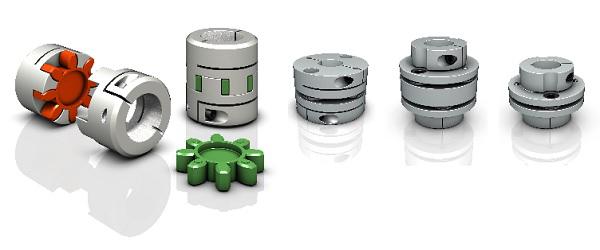
Disc couplings utilize flexible metallic discs to transmit torque and compensate for misalignment. They offer high torsional stiffness, making them suitable for applications requiring precise motion control, such as robotics and CNC machines.
5. Jaw Couplings:
Jaw couplings consist of two hubs with elastomeric spider inserts. They are easy to install, have good misalignment capabilities, and offer electrical isolation between shafts. Jaw couplings are widely used in light to medium-duty applications.
6. Oldham Couplings:
Oldham couplings have three discs—two outer discs with slots and a central disc with a tongue that fits into the slots. They provide excellent angular misalignment compensation while maintaining constant velocity between shafts. Oldham couplings are commonly used in printing machines and conveyors.
7. Beam Couplings:
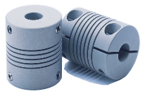
Beam couplings are made from a single piece of flexible material with spiral cuts. They offer good misalignment compensation and torsional flexibility, making them suitable for precision equipment like encoders and servo motors.
The choice of coupling depends on the specific requirements of the application, including torque, speed, misalignment compensation, environmental conditions, and space limitations. Each coupling type has its strengths and limitations, and selecting the right coupling is crucial to ensure optimal performance and reliability in the mechanical system.
“`
Can a Damaged Shaft Coupling Lead to Equipment Failure and Downtime?
Yes, a damaged shaft coupling can lead to equipment failure and downtime in mechanical power transmission systems. Shaft couplings play a critical role in connecting rotating shafts and transmitting power between them. When a coupling becomes damaged or fails to function properly, several negative consequences can arise:
1. Misalignment Issues:
A damaged coupling may no longer be able to compensate for misalignments between the connected shafts. Misalignment can cause excessive vibration, increased wear, and premature failure of bearings and other connected components. Over time, these issues can lead to equipment breakdown and unplanned downtime.
2. Vibration and Shock Loads:
Without the damping properties of a functional coupling, vibrations and shock loads from the driven equipment can transmit directly to the driving shaft and other parts of the system. Excessive vibrations can lead to fatigue failure, cracking, and damage to the equipment, resulting in reduced operational efficiency and increased downtime.
3. Overloading and Torque Transmission:
A damaged coupling may not effectively transmit the required torque between the driving and driven shafts. In applications where the coupling is a safety device (e.g., shear pin couplings), failure to disengage during overloading situations can lead to equipment overload and damage.
4. Increased Wear and Tear:
A damaged coupling can lead to increased wear on other parts of the system. Components such as bearings, seals, and gears may experience higher stress and wear, reducing their lifespan and increasing the likelihood of breakdowns.
5. Reduced System Reliability:
A functional shaft coupling contributes to the overall reliability of the mechanical system. A damaged coupling compromises this reliability, making the system more prone to failures and unplanned maintenance.
6. Downtime and Production Loss:
When a shaft coupling fails, it often results in unscheduled downtime for repairs or replacement. Downtime can be costly for industries that rely on continuous production processes and can lead to production losses and missed delivery deadlines.
7. Safety Hazards:
In certain applications, such as heavy machinery or industrial equipment, a damaged coupling can create safety hazards for workers and surrounding equipment. Sudden failures or uncontrolled movements may pose risks to personnel and property.
Regular inspection, maintenance, and prompt replacement of damaged shaft couplings are essential to prevent equipment failure, minimize downtime, and ensure safe and efficient operation of mechanical systems. It is crucial to address any signs of coupling wear or damage immediately to avoid potential catastrophic failures and costly disruptions to operations.
“`

editor by CX 2024-03-26
by
Leave a Reply