Product Description
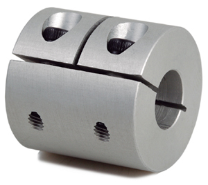
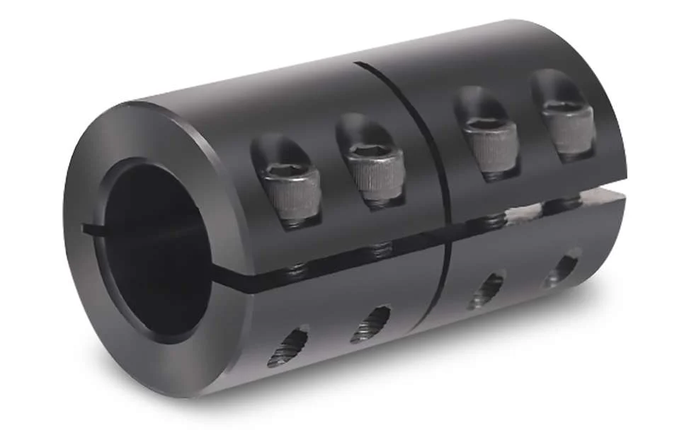
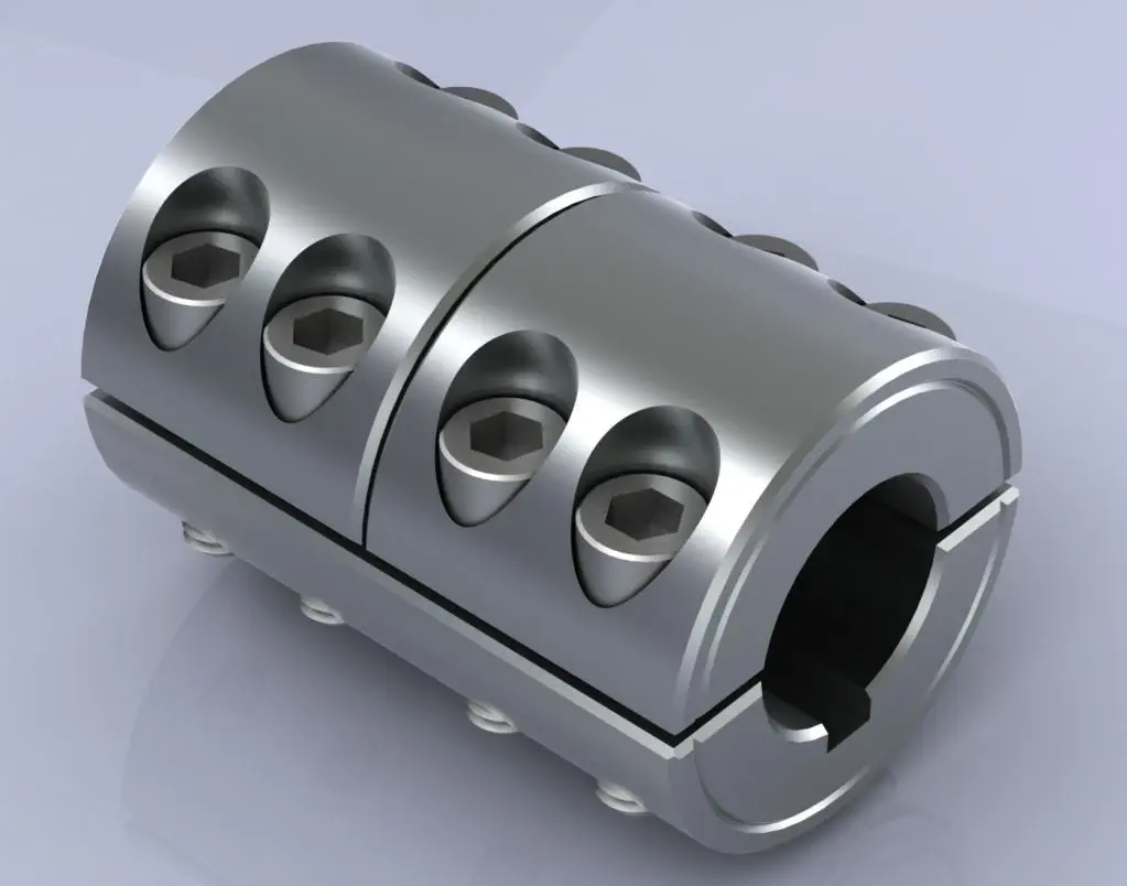
GHC Oldham type coupling cross sliding clamp coupling
Description of GHC Oldham type coupling cross sliding clamp coupling
>The colloid material is imported PA66, which has good wear resistance, corrosion resistance and electrical insulation
>Sliding design can compensate radial and angular deviation more effectively
>Detachable design, easy to install
>Fastening method of clamping screw
Dimensions of GHC Oldham type coupling cross sliding clamp coupling
| model parameter | common bore diameter d1,d2 | ΦD | L | LF | LP | F | M | tightening screw torque (N.M) |
| GHC-16X21 | 4,5,6,6.35 | 16 | 21 | 8.6 | 11.6 | 2.5 | M2.5 | 1 |
| GHC-16X30 | 4,5,6,6.35 | 16 | 30 | 13.1 | 11.6 | 3 | M2.5 | 1 |
| GHC-20X22 | 5,6,6.35,7,8 | 20 | 22 | 8.6 | 12.7 | 2.5 | M2.5 | 1 |
| GHC-20×33 | 5,6,6.35,7,8 | 20 | 33 | 14.1 | 12.7 | 3 | M2.5 | 1 |
| GHC-25×28 | 5,6,6.35,8,9,9.525,10,11,12 | 25 | 28 | 11.7 | 16.65 | 3 | M3 | 1.5 |
| GHC-25X39 | 5,6,6.35,8,9,9.525,10,11,12 | 25 | 39 | 17.2 | 16.65 | 4.2 | M3 | 1.5 |
| GHC-32X33 | 5,6,8,9,9.525,10,11,12.12.7,14,15,16 | 32 | 33 | 14 | 19.5 | 3 | M4 | 2.5 |
| GHC-32X45 | 5,6,8,9,9.525,10,11,12,12.7,14,15,16 | 32 | 45 | 20 | 19.5 | 4.5 | M4 | 2.5 |
| GHC-40X50 | 8,9,9.525,10,11,12,14,15,16,17,18,19 | 40 | 50 | 23 | 18.4 | 7 | M5 | 7 |
| GHC-45X46 | 8,9,9.525,10,11,12,14,15,16,17,18,19,20,22 | 45 | 46 | 21 | 18.4 | 7 | M5 | 7 |
| GHC-50X53 | 10,11,12.7,14,15,16,17,18,19,20,22,24 | 50 | 53 | 24 | 15 | 7.5 | M6 | 12 |
| GHC-50X58 | 10,11,12.7,14,15,16,17,18,19,20,22,24 | 50 | 58 | 26.5 | 17.5 | 8 | M6 | 12 |
| GHC-55X57 | 10,11,12.7,14,15,16,17,18,19,20,22,24,25,28,30,32 | 55 | 57 | 26 | 17.5 | 7.8 | M6 | 12 |
| GHC-63X71 | 14,15,16,17,18,19,20,22,24,25,28,30,32 | 63 | 71 | 33 | 24 | 10 | M8 | 20 |
| GHC-70X77 | 14,15,16,17,18,19,20,22,24,25,28,30,32,35,38 | 70 | 77 | 29.5 | 25 | 12 | M8 | 20 |
| model parameter | Rated torque (N.M)* |
allowable eccentricity (mm)* |
allowable deflection angle (°)* |
allowable axial deviation (mm)* |
maximum speed rpm |
static torsional stiffness (N.M/rad) |
moment of inertia (Kg.M2) |
Material of shaft sleeve | Material of shrapnel | surface treatment | weight (g) |
| GHC-16X21 | 0.7 | 0.8 | 3 | ±0.2 | 8500 | 30 | 5.5×10⁻⁷ | High strength aluminum alloy | P A 6 6 | Anodizing treatment | 8 |
| GHC-16X30 | 0.7 | 0.8 | 3 | ±0.2 | 9000 | 30 | 5.9×10⁻⁷ | 12 | |||
| GHC-20X22 | 1.2 | 1.2 | 3 | ±0.2 | 6500 | 58 | 1.3×10⁻⁶ | 13 | |||
| GHC-20×33 | 1.2 | 1.2 | 3 | ±0.2 | 7000 | 58 | 1.5×10⁻⁶ | 19 | |||
| GHC-25X28 | 2 | 1.6 | 3 | ±0.2 | 5500 | 130 | 4.0×10⁻⁶ | 24 | |||
| GHC-25X39 | 22 | 1.6 | 3 | ±0.2 | 6000 | 130 | 4.5×10⁻⁶ | 35 | |||
| GHC-32X33 | 4.5 | 2 | 3 | ±0.2 | 4500 | 270 | 1.3×10⁻⁵ | 48 | |||
| GHC-32X45 | 4.5 | 2 | 3 | ±0.2 | 4800 | 270 | 1.5×10⁻⁵ | 67 | |||
| GHC-40X50 | 9 | 2.4 | 3 | ±0.2 | 3600 | 520 | 4.2×10⁻⁵ | 114 | |||
| GHC-45X46 | 12 | 2.5 | 3 | ±0.2 | 3500 | 800 | 4.5×10⁻⁵ | 140 | |||
| GHC-50X53 | 19 | 2.6 | 3 | ±0.2 | 3000 | 800 | 1.0×10⁻⁴ | 190 | |||
| GHC-50X58 | 19 | 3 | 3 | ±0.2 | 3000 | 800 | 1.1×10⁻⁴ | 215 | |||
| GHC-55X57 | 25 | 3.2 | 3 | ±0.2 | 3000 | 900 | 1.3×10⁻⁵ | 260 | |||
| GHC-63X71 | 33 | 3 | 3 | ±0.2 | 2550 | 1200 | 3.5×10⁻⁴ | 455 | |||
| GHC-70X77 | 56 | 3.5 | 3 | ±0.2 | 2500 | 1260 | 4.1×10⁻⁵ | 520 |
/* January 22, 2571 19:08:37 */!function(){function s(e,r){var a,o={};try{e&&e.split(“,”).forEach(function(e,t){e&&(a=e.match(/(.*?):(.*)$/))&&1

Can Rigid Couplings Accommodate High Torque and High-Speed Applications?
Yes, rigid couplings are well-suited for high torque and high-speed applications. Their design and construction allow them to efficiently transmit large amounts of torque and handle high rotational speeds without compromising performance or introducing backlash.
Rigid couplings are typically made from robust materials, such as steel or aluminum, which provide high strength and stiffness. This allows them to withstand substantial torque loads without deformation or failure. Additionally, rigid couplings do not have flexible elements, such as elastomers or springs, which can be a limiting factor in high-torque applications.
The absence of flexible elements also means that rigid couplings have minimal backlash. Backlash is the clearance between mating teeth in a coupling and can cause position inaccuracies, especially in high-precision systems. Since rigid couplings have a solid, one-piece design, they offer precise and immediate torque transmission, making them suitable for applications requiring high accuracy and repeatability.
Furthermore, the solid construction of rigid couplings allows them to handle high rotational speeds. They do not exhibit the bending or torsional flexibility seen in some other coupling types, which can be limiting factors in high-speed applications. As a result, rigid couplings are commonly used in various high-speed machinery, such as power transmission systems, motors, pumps, and industrial equipment.
However, it is essential to ensure proper alignment and installation when using rigid couplings in high-torque and high-speed applications. Any misalignment between the shafts can lead to increased stresses and premature failure. Regular maintenance, including shaft alignment checks, can help ensure optimal performance and longevity in such demanding applications.
In summary, rigid couplings are an excellent choice for high torque and high-speed applications due to their robust design, minimal backlash, and ability to provide precise torque transmission. When correctly installed and maintained, rigid couplings can reliably handle the demands of various industrial and mechanical systems.

Impact of Rigid Coupling on the Overall Reliability of Connected Equipment
A rigid coupling plays a crucial role in enhancing the overall reliability of connected equipment in mechanical systems. Here’s how it positively impacts reliability:
1. Power Transmission Efficiency: Rigid couplings provide a direct and efficient connection between the shafts of the connected equipment. With no flexible elements, there is minimal power loss, ensuring efficient power transmission from one shaft to another.
2. Elimination of Backlash: Rigid couplings have zero backlash, which is crucial in precision applications. Backlash, which is the play or clearance between connected components, can cause inaccuracies in motion control systems. With a rigid coupling, any movement is directly transferred, maintaining precise positioning.
3. Zero-Maintenance Option: Some rigid couplings are designed to be maintenance-free. They do not require lubrication or periodic adjustments, reducing downtime and ensuring continuous operation.
4. High Torque Transmission: Rigid couplings can handle high torque loads, making them suitable for heavy-duty applications. Their robust construction ensures reliable torque transmission without failure or slippage.
5. Resistant to Misalignment: While rigid couplings offer no flexibility, they are excellent at handling axial misalignment and angular misalignment, provided it falls within their design limits. This ability to tolerate some misalignment enhances reliability and reduces the risk of component damage.
6. Vibration Damping: The stiffness of rigid couplings aids in damping vibrations generated during operation. By minimizing vibrations, the coupling helps protect connected equipment from excessive stress and fatigue failure.
7. Increased System Stiffness: Rigid couplings contribute to the overall stiffness of the mechanical system. This stiffness improves the dynamic response of the system and reduces the likelihood of resonance, leading to more reliable operation.
8. Simple and Compact Design: Rigid couplings have a straightforward and compact design, which reduces the chances of component failure or wear. Their simplicity makes them easy to install and maintain, further enhancing system reliability.
9. Suitable for High-Speed Applications: Rigid couplings are well-suited for high-speed applications due to their ability to maintain accurate shaft alignment and transmit torque efficiently.
10. Compatibility with Various Industries: Rigid couplings find applications in a wide range of industries, including automotive, aerospace, manufacturing, and more. Their versatility and reliability make them a popular choice in demanding industrial environments.
Overall, the use of a properly selected and installed rigid coupling enhances the reliability of connected equipment by providing a robust and efficient connection between shafts. It ensures precise power transmission, reduced maintenance requirements, and improved system performance, leading to increased overall reliability and uptime of the mechanical system.

Types of Rigid Coupling Designs:
There are several types of rigid coupling designs available, each designed to meet specific application requirements. Here are some common types of rigid couplings:
- 1. Sleeve Couplings: Sleeve couplings are the simplest type of rigid couplings. They consist of a cylindrical sleeve with a bore in the center that fits over the shaft ends. The coupling is secured in place using setscrews or keyways. Sleeve couplings provide a solid and rigid connection between shafts and are easy to install and remove.
- 2. Clamp or Split Couplings: Clamp couplings, also known as split couplings, are designed with two halves that fit around the shafts and are fastened together with bolts or screws. The split design allows for easy installation and removal without the need to disassemble other components in the system. These couplings are ideal for applications where the shafts cannot be easily moved.
- 3. Flanged Couplings: Flanged couplings have flanges on each end that are bolted together to form a rigid connection. The flanges add stability and strength to the coupling, making them suitable for heavy-duty applications. They are commonly used in industrial machinery and equipment.
- 4. Tapered Couplings: Tapered couplings have a tapered inner diameter that matches the taper of the shaft ends. When the coupling is tightened, it creates a frictional fit between the coupling and the shafts, providing a rigid connection. These couplings are often used in applications where high torque transmission is required.
- 5. Marine or Clampshell Couplings: Marine couplings, also known as clampshell couplings, consist of two halves that encase the shaft ends and are bolted together. These couplings are commonly used in marine applications, such as propeller shafts in boats and ships.
- 6. Diaphragm Couplings: Diaphragm couplings are a type of rigid coupling that provides some flexibility to accommodate misalignment while maintaining a nearly torsionally rigid connection. They consist of thin metal diaphragms that transmit torque while compensating for minor shaft misalignments.
The choice of rigid coupling design depends on factors such as shaft size, torque requirements, ease of installation, and the level of misalignment that needs to be accommodated. It is essential to select the appropriate coupling design based on the specific needs of the application to ensure optimal performance and reliability.


editor by CX 2024-04-11
by
Leave a Reply